- By John Gerry, P.E.
- February 03, 2003
- ExperTune Inc
- ExperTune Inc.
- News
Summary
-
Choosing the proper filter can have an impact in your company's bottom line.

by John Gerry, P.E.
Click here to see the complete presentation in more detail as a web-cast.
The best PV filter type
In general, the best type of filter is a second order Butterworth, but a simple first order filter can do much to reduce controller output jitter and save the life of your valve or variable frequency drive. Since most systems have first order filters built in, it is usually a good choice.
The best PV filter size
In general, the optimal size PV filter is the largest one that does not degrade the performance of the loop. There are always tradeoffs in process control and choosing the filter type and size are one of them.
Filter types
First Order Filter
The most common filter is a first order filter. The first order filter is simply a lag. Here are sample difference equations for one way to do a first order filter:
   PVf = PV + LagTime * (PVf1 - PV) / (LagTime + SampleInterval)

	PV=process variable
	LagTime= lag time (filter time constant found by ExperTune)
	SampleInterval = calculation interval for this lead lag code
	PVf=filtered PV
	PVf1=last value of PVf
Averaging Filter
Averaging filters are probably the second most common filter. Averaging filters simply average a number of values in the past to find the averaged value for this sample.
Value for this sample = Average of a set amount of past values
Averaging filters will completely remove cycles at the period of the averaging time. However, to get similar high frequency noise reduction as first order filters, filtering times must be twice as large as the first order one. So, usually a first order filter is a better choice than the averaging one.
Second Order Filters
Second order filters provide dramatically more noise reduction at high frequencies, but less at intermediate frequencies. To get a second order filter, simply cascade a couple of first order ones. To set the second order filter, use a LagTime set to half what you would use for a first order one.
Filtering Increases Valve Life

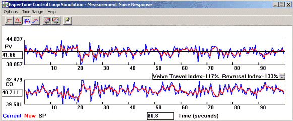
The time response graph above are from a simulated flow loop. The red lines show the response when the loop has a first order PV filter. Blue lines are for a system without PV filtering. The graphs represent normal operating conditions for the flow loop. The upper graph in this window is the filtered and unfiltered PV. The filtered PV is quieter. In the lower graph are the controller outputs. With the filter, the controller output moves less and is smoother.

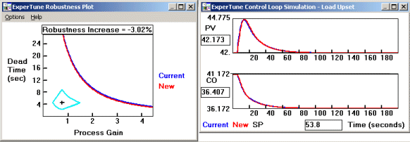
The analysis graphs above are from the same flow loop. Red is with filtering, blue is without. The robustness and setpoint time response show that we give up very little to get a smoother controller output. You can barely see the blue lines behind the red ones on these plots.
A complete tutorial on Robustness plots is the subject of a previous presentation, "Loop Stability - the other half of the PID Tuning Story".
The optimal filter time is the one that reduces the controller output movement the most, but hurts the control loop performance the least. This can be a delicate balance. Increase the filter time to the extreme and it becomes the dominant lag in your control loop. The controller would be working to control mainly the filter and if you are displaying the filtered PV, you are really misleading operations about what the PV really is. Too small a filter time and the valve wears out earlier than it could.

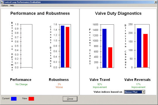
The proper filter can make a big difference in valve wear. Lets look at the flow loop example again. From this example, the tradeoff of performance vs. valve wear is nicely seen in the bar graphs above. The red bars are with the filter, blue is without. On the right hand side are two bar graphs under the heading Valve Duty Diagnostics. Valve travel is the distance in percent that the valve travels.
In the valve travel bars, you can see the red bar (this is the system with the filter) is half the height of the blue bar showing that valve travel is cut by more than half or a 92% improvement. Reversals are the number of times the valve changes direction. Reversals are also cut by more than half. At the same time, the performance is unchanged and robustness is only slightly effected. So the addition of a first order filter dramatically reduces the valve wear.
Setting the filter time:
The filter time should always be set less than the process dead time.
PV filter < process dead time
If you use derivative action then do not set the filter larger than about 1/10 the derivative time of the controller. For parallel controllers these rules apply only when the controller gain is near one. It is better to err on the side of too small a filter.
PV filter < (Derivative time)/10
Often times transmitter filters are set too large and severely degrade control.
A tutorial on PID algorithms is the subject of a previous presentation, "Differences in PID Algorithms and Units".
Conclusions
Choosing the proper filter can have an impact in your company's bottom line.
ExperTune software makes all this easy. ExperTune PID Tuner automatically finds the largest filter to use in the control loop without degrading response and robustness. ExperTune software also includes performance, valve wear, and simulation comparisons so you can decide for yourself about the tradeoffs in your control loop.
Click here to see this full presentation as a web-cast.
Click here for more information on ExperTune software. Or email, Tom Kinney, (262) 628-0088
Click Here for More InformationDid you enjoy this great article?
Check out our free e-newsletters to read more great articles..
Subscribe

