- By John Gerry, P.E.
- February 03, 2003
- News
Summary
-
ExperTune’s Loop Tuner/Analyzer, automatically checks your loop’s sample interval and tells you if it needs to be changed.

by John Gerry, P.E.
Click here to see the complete presentation in more detail as a web-cast.
The short answer to the question of sample interval is to sample between 4 and 10 times faster than the process dead time. 4 times faster being barely adequate and 10 times faster being the best.
Ideal Sample Interval = (Process Dead Time)/10
It is better to err on the side of being too fast. This applies both for what your industrial digital controller should sample at and how fast to collect data for analysis, modeling and PID tuning.
Sampling Too Slow
Now for a more in depth look. If you don't collect the data fast enough then you will be "hiding" data from the controller or analysis software. Imagine if you attempted to drive your car by looking at the road once every 5 seconds.
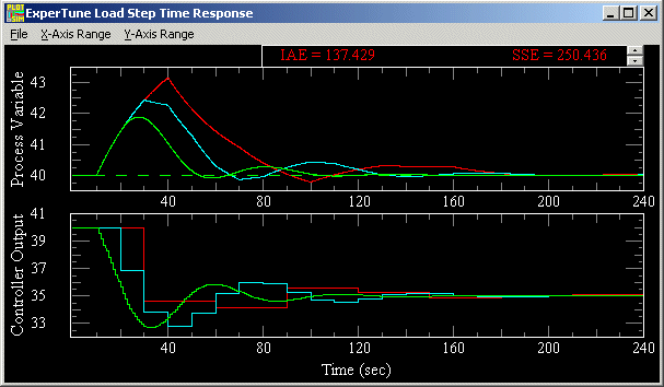
The limiting factor in process control is dead time. Sampling adds about 1/2 the sample time to the process as dead time. The red line in the plot below shows the optimal response of a loop to a disturbance. The controller in this loop is sampling 3 times slower than the process dead time. (process dead time = 10 sec., time constant = 30 sec. Controller sampling at 30 sec.) The controller does nothing about the upset until a time of 30 leaving 20 seconds of time when it was blind to the upset.

The cyan line in the plot shows the same loop with the same disturbance, but this time the controller is sampling faster. The controller is now sampling at the same rate as the dead time. The controller tuning is the same in both loops. The response is 30% faster simply because we made the sample interval faster.
The green line in the plot below, again is for the same loop and disturbance, but this time with a sample interval at 10 times faster than the process dead time. This sample interval is now properly set. The response is almost twice as fast as that with the sample time equal dead time. About 20% of the improvement in response was because we were able to adjust the tuning to be faster. The tuning of all three loops has roughly the same robustness or sensitivity to process changes.
If you use the ExperTune Loop Analyzer, the software checks your sample interval and recommends the optimal interval to use.
Aliasing and Sampling Hyper-Fast
Now lets look at why some people feel they need to sample extremely fast - at times approaching 1 millisecond for loops that have dead times of 2 or 3 seconds. This would be sampling at 2000 times faster than the dead time.

The phenomena they are trying to avoid is called aliasing. Aliasing or "ghost signals" are a real problem. Take a look at the plot. We are sampling the cyan sign wave signal at a rate shown by the gray vertical lines. At each sample interval, we get an actual value shown by a red blob in the graph above.

When you connect the dots, you get the slow sine wave shown in yellow. But this slow sine wave is not in the original signal. The yellow sine wave reveals a ghost or alias signal that is not in the analog signal.
One attempt at solving the aliasing problem is to sample extremely fast and then apply a digital filter on the hyper-collected data. This would eliminate aliasing in frequencies below the hyper-sampling frequency but would not eliminate aliasing occurring at higher frequencies
On higher frequency noise, aliasing signals would still come through. Extremely fast data collection equipment is more costly, and the amount of data collected uses lots of hard drive space, making it hard to transfer the data to different machines and takes more time to process. Isolating the signals that are sampled fast adds additional cost, so the tendency is to omit this safety hardware when hyper-sampling.
Collecting data faster than control loop is going is usually wasted data since the controller cannot react to the resultant tuning.
Fortunately the complete solution for aliasing is simple and has been around a long time. Simply add an analog filter or anti-aliasing filter to the signal before it is digitized. The analog filter completely decimates higher frequency signals that leaked through on the previous hyper-sampling attempt. Most I/O for most distributed control systems have analog anti-aliasing filters. They may simply be called a filter. In much I/O, analog filters are set to reduce noise most drastically in the 50-60 Hz range. In the above example if we apply a simple first order filter with a time constant of 1/2 the sample interval the aliasing gets reduced by a factor of 6, reducing the level probably below the resolution of the analog to digital converter.
Conclusions
Sampling at the proper rate will allow optimal control of your loop. ExperTune’s Loop Tuner/Analyzer, automatically checks your loop’s sample interval and tells you if it needs to be changed.
Click Here for More InformationDid you enjoy this great article?
Check out our free e-newsletters to read more great articles..
Subscribe

