


Flow measurement is one of the most important readings in most chemical and other process plants, and there are many different technologies available for these applications. This article will examine vortex flow technology, which provides advantages in many applications, including critical safety-related situations. The world of process instrumentation is built on the ways in which certain mechanical and electrical characteristics can be used by sensors and transmitters to quantify critical variables, such as fluid flow. When a shedder bar (Figure 1) is introduced in a pipe perpendicular to the flow, the fluid creates alternating vortices. This is described as the Von Kármán effect, and the frequency is proportional to fluid velocity for gas, liquid, or steam.
 Measuring vortex frequency requires a small sensing element called a flexure (Figure 2). The vortices cause it to oscillate, and a piezoelectric sensor converts this mechanical motion into a frequency electrical signal, which is fed to the transmitter and converted to velocity. The velocity is then multiplied against the interior cross section to calculate volumetric flowrate. Some manufacturers incorporate the flexure entirely within the shedder bar, eliminating the sensor as a potential leak point and ensuring long operational life.
Multivariable capabilities
A vortex flow meter alone delivers a volumetric reading, but if combined with temperature and line pressure data, a sophisticated transmitter can calculate additional mass flow variables, especially useful for compressible fluids. The temperature sensor provides compensation for saturated steam, and an additional pressure input compensates for superheated steam (Figure 3).  These capabilities are especially useful when working with steam, both saturated and superheated, or when calculating mass flow of fuel gas to determine energy content. Temperature and pressure data can be fed directly to the vortex flow meter transmitter if it has the internal capability to carry out the required calculations.
Why vortex?
All flow meter technologies present a balance of pros and cons in a variety of applications, and vortex technology has a long list of positives. From a performance standpoint, they are similar to differential pressure (DP) designs, so they can often be considered on similar terms in many applications, however vortex technology offers important additional advantages, including:
- Versatile measurement for any fluid type, including liquids, gases and steam
- Low pressure drop plus clog resistance because the shedder bar has a narrow profile
- Low power consumption allows operation with two-wire loop power or FOUNDATION Fieldbus
- High turndown range, usually at least 20:1, but often up to 30:1
- Scalable with pipe sizes ranging from ½ inch to 14 inch as standard offerings
- Compact body configuration fits in tight spaces
- Tolerant of turbulence, eliminating the need for long straight pipe runs upstream or downstream
- Leak resistant due to a single-piece body without gaskets
- Internal fluid containment with no impulse lines to freeze, leak, or clog
- Few wetted parts make construction with specialized materials practical
- High strength construction withstands high pressures and temperatures
- Body design allows for a fully sealed flow path, allowing maintenance to remove, inspect and reassemble components of the meter, including the piezoelectric sensor and integrated temperature sensor, while the process is operating.
Vortex designs do have limitations in two areas, both of which are common issues with most types of flow meter technologies. First, vortex flow meters may have challenges with mixed-phase fluids, so it is recommended that the process media be either gas, liquid, or steam. The transmitter requires correct programming to convert velocity into appropriate engineering units. Some transmitters can detect when the fluid has changed state and can warn operators of the development. Second, maintaining factory-specified accuracy requires a minimum fluid velocity to excite the flexure enough to create an accurate and repeatable reading.
Working within the published turndown range should be sufficient to support the desired degree of accuracy, but some applications may present a velocity lower than is practical. For these situations, it may be necessary to use a smaller sensor to create sufficient velocity.
Safety applications
Process units are invariably supported by a safety instrumented system (SIS), which is a collection of individual safety instrumented functions (SIFs) designed to take the process to a safe state in the event of an incident. Most SIFs relate to temperature and pressure, but flow can also create hazards as out-of-control flow or no flow at all can result in incidents. Consequently flow-related SIFs tie a flow meter to final control elements, such as changing valve settings, turning off a pump, or redirecting flow. This can’t be just any flow meter since a SIF must use a device certified for SIS applications. Sensors, instruments, controllers, valves and others can be purchased with such designations, including a safety integrity level (SIL) number.
The concept underlying safety-certified devices is not that they can’t fail. Safety engineers know that anything can fail, but for safety applications, it is important to understand how something might fail, along with its probability of failing. To earn a safety certification, a device is subjected to a battery of tests listed in safety standard IEC 61508 to determine the probability of failure on demand (PFD). Such tests are performed by specialized agencies, independent of the manufacturer. Certification means the testing agency is convinced that when the instrument must handle an actual problem the PFD is low enough that the instrument can be part of a SIS, providing a reliable layer of protection for the plant.
The PFD rating places it into a SIL category, usually either SIL 2 or SIL 3, which must match the application’s criticality.
Avoiding false alarms
Depending on the nature of a given process, a SIF might do something as minor as adjusting a valve, but it could also shut down a process entirely or activate a fire suppression system. These actions can be hugely disruptive to production, but necessary to protect the facility, its people and surrounding community. Still, the last thing a facility wants is a false alarm, launching a disruptive and costly response for no reason. Just as a safety certified instrument must examine the possibility of failure on demand, the idea of trigging unnecessarily is also a consideration. Where a safety certified instrument causes a false alarm, operators may be tempted to make an unauthorized change to the setpoint.
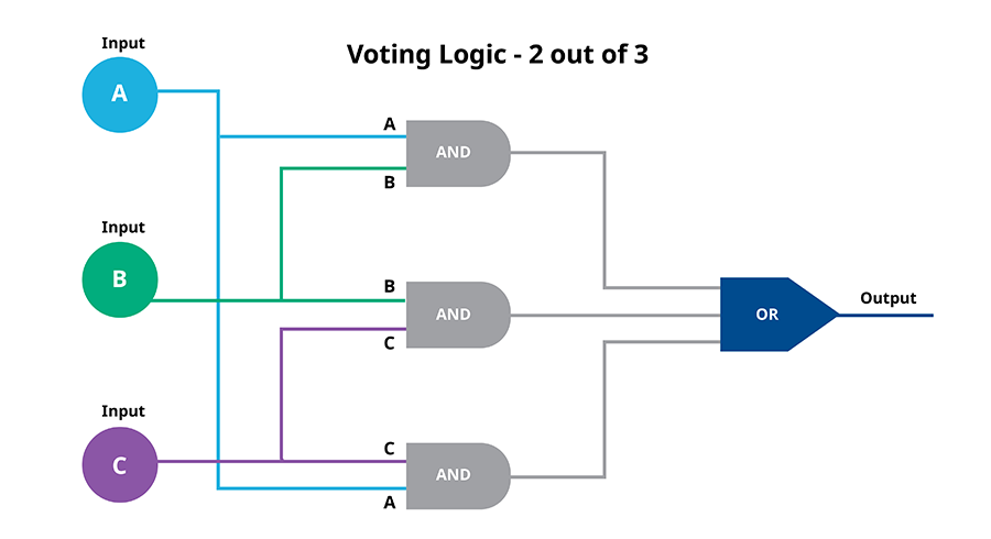
Under such conditions, it may lose its ability to respond to a true emergency. A more desirable solution is to use a voting scheme with multiple instruments measuring the same variable. The best combination of protection and practicality is a two-out-of-three (2oo3) approach (Figure 4) where three identical, but independent, safety-certified instruments measure the same critical variable. For the response to trigger, two of them must act simultaneously. This avoids a situation where only one creates a false alarm.
 Configuring and installing a 2oo3 flow measurement scheme can be cumbersome and costly, but the effects of an unneeded response can be far worse. One major advantage of vortex flow meters is their compact design, making it easy to fit multiple units in a relatively small space (Figure 5). In this configuration, opposing transmitters share a single shedder bar, but their function is sufficiently separated so each acts independently. This configuration is approved by safety evaluators and has received a SIL 3 rating for critical applications. A fourth transmitter provides the same reading to the automation host system, so only three of the transmitters need to be safety certified.
 This type of configuration is only possible because of vortex design flexibility. For example, some sites have assembled DP setups using a single orifice plate surrounded by four DP transmitters, but this creates complex arrangements of impulse lines. Worse, the orifice plate becomes a single point of failure for all the transmitters, increasing the PFD and reducing the possible SIL rating.
Optimizing flow measurement applications
Any engineer laying out a strategy for measuring flow must optimize a collection of process trade-offs for each technology under consideration.
- What level of accuracy is necessary?
- Is the fluid compressible?
- Is the flow rate generally stable, or highly variable?
- Is the fluid clean or can there be debris?
- How complex is the piping?
- What are likely pressure and temperature conditions?
The list goes on, and each technology will provide a slightly different set of answers to the questions. Users must weigh these during the selection to suit process requirements while minimizing cost, technical drawbacks and measurement limitations. Vortex flow meters provide a range of capabilities that are difficult to duplicate with any other approach. Most other flow meter technologies cannot match its wide operational capabilities, simplicity of construction, ease of installation and low lifetime cost. Vortex is also a very reliable technology, so it rarely needs to be removed and replaced, a significant advantage in many applications.
Other advantages, which emerge when multiple flow meters are required, are its small form factor, and its minimal requirements for specialized piping configurations to enable installation and operation. Quad vortex flow instruments leverage all these advantages to deliver the performance required in demanding SIS applications. Overall, vortex flow meters provide a range of capabilities, operational economy and form factor advantages difficult to duplicate with any other flow measurement technology. All figures courtesy of Emerson except as noted
