


In many mechanical systems, precise motion hinges upon effective monitoring and control of the motor. Encoders make motion control possible by sensing the motor’s speed and position and sending feedback signals to control components. Two square waves, or channels, shifted 90 electrical degrees from each other, along with an optional index pulse that occurs once per revolution, encode the angular position data. This article will provide an overview of two common types of encoders: optical encoders and magnetic encoders.
Where you’ll find encoders
Encoders are used most anywhere you’ll find electric motors. Here is just a small sample of the many applications that incorporate encoders:
-
Drug delivery systems. A drug delivery system requires a precise amount of medication at a specified speed. During the development process of the pump, feedback is used to determine the required motor speed needed to deliver the proper amount of medication.
-
Automated window shades. The mechanism that provides automatic speed and position control incorporates an encoder. Console settings are developed based on the motor speed requirement to move the shade into the desired position.
-
Electronic assembly equipment. Surface mount (SMT) pick and place equipment in automated assembly lines must deliver high throughput. Motion control systems detect various sizes and weights of the components being placed on the printed circuit board (PCB) prior to soldering. The motors used in these systems operate in sync, relying on encoder feedback to ensure that all varying components are picked up and placed on the PCB at the same time.
-
Robotics. Encoders play an important role in robotics, helping to ensure precise control of pressure and speed for gripping arms without damage to workpieces. Because varying speeds and pressures are required for gripping, encoders help engineers understand motor speed and position of grippers to create accurate motion profiles.
What you’ll find on the datasheet
Here is a quick review of some of the typical specifications you’ll find on an encoder datasheet to help you select the best encoder for your application: Number of lines available. This specification is used to determine encoder resolution. Portescap datasheets use the expression, “line = pulse” to indicate the number of square cycles per channel. For example, the MR2 encoder can provide up to 512 lines per revolution. One line, or pulse, has four counts, quadrature.
Counts correspond to the minimum angular step. Therefore, the MR2 encoder has 2,048 counts — or angular steps. 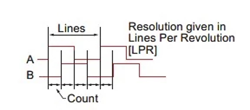 Duty cycle. Also referred to as “period,” a duty cycle is typically 360 degrees of rotation.
  Supply voltage, supply current.
The amount of voltage or current required for the encoder to perform properly. Output signals. Two or more signals that indicate when an encoder moves and its direction of movement. Many Portescap encoders have two output signals—channel A and channel B. Some encoders also have a third channel designated as an index channel—or channel Z—with one line per revolution and synchronization to the A/B channel.
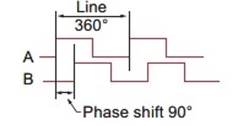
This index can be used to determine a reference position. 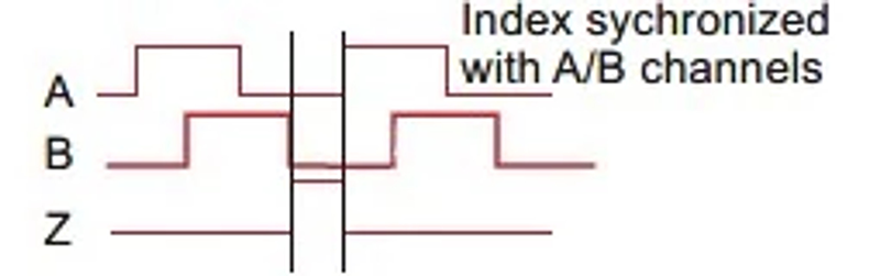 Phase shift. For many encoders, including Portescap products, channels A and B have a 90-degree angle phase difference. In this diagram, channel A leads channel B, showing a clockwise rotation. Channel B leading channel A indicates a clockwise direction.
Optical and magnetic encoder examples
This is a summary of some of the features and benefits that optical and magnetic encoders can provide, using just a few examples from Portescap’s product lineup:
-
Incremental Optical Encoder. A dedicated ASIC, composed of optoelectronic sensors, receives infrared (IR) light emitted from an LED and passed through a metal disc—known as a codewheel—with both opaque and clear segments in order to provide very precise positioning without sensitivity to external magnetic fields.
-
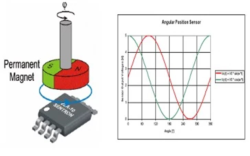
Magnetic Encoder. Portescap’ MR2 integrates a magnetoresistive sensor to provide sin/cosine magnetic field measurements. This encoder is not affected by temperature and exhibits a low sensitivity to unwanted external fields. Resolution up to 512 lines is available.
-
M-sense Magnetic Encoder. This compact encoder uses just a single chip to provide three channels of feedback and includes an RS-422 line driver. A Hall sensor array senses the magnetic field, and the sin/cosine signal is digitized and converted into an ABZ incremental signal. The resolution ranges from one to 1,024 lines per revolution.
‘ 
Encoder feedback ensures precise motor control
Designers of motor-driven systems have come to rely on encoders to provide feedback in response to motor speed as well as the direction and position of the rotor. This feedback is used to develop control systems for the final product. Portescap offers robust optical and magnetic encoders that stand up to severe environments and can deliver resolutions from four to 1,024 lines per revolution, with up to three channels. For more information about Portescap encoders, visit our product page .