AutoQuiz is edited by Joel Don, ISA's social media community manager.
This automation industry quiz question comes from the ISA Certified Control Systems Technician (CCST) program . Certified Control System Technicians calibrate, document, troubleshoot, and repair/replace instrumentation for systems that measure and control level, temperature, pressure, flow, and other process variables. Click this link for more information about the CCST program.
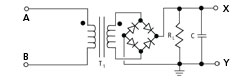
In a full-wave bridge rectifier circuit used in power supplies, as shown in the post image, which statement below is true?
a) the input current between terminals A and B is a sinusoidal AC current, and the output voltage between terminals X and Y is an inverted AC voltage b) the output voltage between terminals A and B is an AC voltage, and the input current between terminals X and Y is a square-wave DC current c) the output voltage between terminals A and B is a constant DC voltage, and the input current between terminals X and Y is a sinusoidal AC current d) the input current between terminals A and B is a sinusoidal AC current, and the output voltage between terminals X and Y is a constant DC voltage e) none of the above
Answers B and C cannot be correct, since Terminals A and B are used for the input current to the transformer circuit. Answer A is not correct since the output from the diode bridge and RC filter circuit is a DC voltage, not an inverted AC voltage.
The correct answer is D
. The input current between terminals A and B is a sinusoidal AC current, and the output voltage between terminals X and Y is a constant DC voltage. The transformer accepts an AC current. The diode bridge rectifies the sinusoidal waveform of the AC current and produces a DC ripple voltage, but the RC filter circuit smoothes out the voltage pattern to give the constant DC voltage shown in the figure below.
Reference
: Thomas A. Hughes; Measurement and Control Basics, 5th Edition , ISA Press.

About the Editor
Joel Don is the community manager for ISA and is an independent content marketing, social media and public relations consultant. Prior to his work in marketing and PR, Joel served as an editor for regional newspapers and national magazines throughout the U.S. He earned a master's degree from the Medill School at Northwestern University with a focus on science, engineering and biomedical marketing communications, and a bachelor of science degree from UC San Diego .
Connect with Joel
![]()
![]()
![]()