Ask any project manager who has delivered a large gas metering skid, and they will describe the same frustration: the ultrasonic flowmeter arrives from the manufacturer weeks before the meter run spool is ready. The calibration facility is booked, the third-party inspector is on standby, and the engineers are waiting — but without the spool, nothing moves. Calibration is a bottleneck in the critical path, and every day of spool fabrication delay becomes a day of project delay.
This is not an edge case. It is a structural feature of how custody transfer metering projects are traditionally sequenced, and it carries real commercial consequences. Delays in commissioning large natural gas metering systems translate directly into deferred transmission revenues, contractual penalties, and reputational risk for project delivery teams.
Surrogate spool calibration offers a proven, standards-compliant path out of this bottleneck. By calibrating the ultrasonic meter against a hydraulically equivalent spool permanently installed at an accredited laboratory — rather than waiting for the project-specific spool — calibration and spool fabrication can proceed in parallel. The result, based on project experience across major gas infrastructure installations in Saudi Arabia and the wider Middle East, is a schedule reduction of approximately 11 weeks per metering system in real-world scenarios where spool material is delayed — potentially much more where spool fabrication faces supply chain delays or complex inspection requirements. There is no compromise to measurement accuracy or regulatory compliance.
Why ultrasonic meters need laboratory calibration
Custody transfer ultrasonic flowmeters (USMs) are the dominant technology for commercial measurement of natural gas at high-pressure pipeline handover points. They operate on the transit-time principle: pairs of transducers mounted in the pipe wall transmit acoustic signals in both upstream and downstream directions. Because a flowing gas medium carries the acoustic signal with it, the downstream travel time is shorter than the upstream travel time. The meter calculates the path-average velocity for each acoustic path from the difference between these travel times. The meter’s firmware then applies a numerical integration algorithm — weighted to the geometric positions of all four to six measurement paths across the pipe cross-section — to derive the cross-sectional mean velocity. The meter multiplies this mean velocity by the known pipe cross-sectional area to determine the volumetric flow rate.
Modern custody transfer USMs typically employ four to six measurement paths at different radial and angular positions. This multipath architecture reduces sensitivity to nonuniform flow profiles and provides rich internal diagnostic data — path velocity ratios, swirl indicators, and speed-of-sound consistency — that can confirm measurement integrity during calibration and field operation.
The accuracy of a USM is critical and depends on the match between the velocity profile during calibration and the velocity profile in field service. If those profiles differ significantly, the meter factor derived in the laboratory will not hold in the field. This is why calibration standards — American Gas Association (AGA) Report No. 9 and International Organization for Standardization (ISO) 17089-1:2019 — require that meters be calibrated at accredited facilities under controlled hydraulic conditions that replicate the intended installation environment.
Calibration is not a procedural checkbox. It is the process by which the meter’s numerical integration algorithm is validated against known flow rates, and the resulting meter factor is determined. Get the calibration conditions wrong, and the meter factor will carry a systematic error into service. Get them right, and the calibration is robust, traceable and defensible to fiscal authorities.
 Figure 1: Conventional calibration workflow — sequential execution. Calibration begins only after spool fabrication is complete. The total project duration is approximately 35 weeks (real-world scenario with delayed spool material).
The sequential trap: How conventional workflows create schedule risk
A conventional custody transfer metering project follows a largely sequential execution path. The ultrasonic meter is manufactured and factory-acceptance tested. The meter run spool is then engineered, materials are procured, and fabrication begins. Fabrication involves precision machining of the internal bore, certified welding, post-weld heat treatment where required, nondestructive examination, dimensional inspection, and full documentation. Only after all of this is the spool released for shipment to the calibration laboratory. In a representative project, the total time from meter manufacturing through calibration completion and return to the skid assembly yard can reach 35 weeks in a real-world scenario where spool material is delayed and the calibration slot is missed. The critical dependency is clear: calibration cannot begin until the spool is available. Any slippage in spool fabrication, such as material delays, inspection hold points or rework, propagates directly into the project delivery date.
For projects with tight commissioning windows — driven by plant start-up constraints, contractual milestones, or regulatory requirements — this sequential vulnerability represents meaningful commercial risk. On multi-train projects where several meter runs are required, modest individual delays can compound into significant overall schedule overruns.
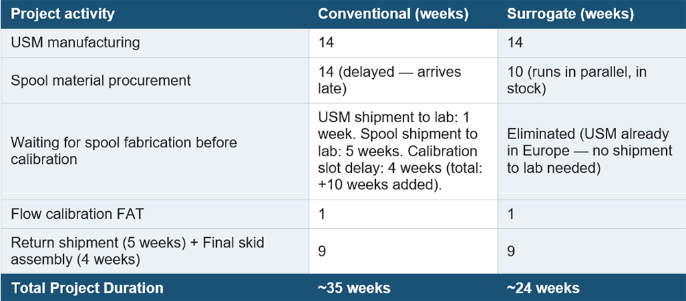 Table 1: Project schedule comparison — conventional versus surrogate spool calibration (real-world delayed spool scenario). A saving of approximately 11 weeks that grows with every additional week of spool fabrication delay.
 Figure 2: Surrogate spool calibration workflow — parallel execution. Calibration and spool fabrication proceed concurrently. The total project duration is approximately 24 weeks, minimum. The schedule savings are approximately 11 weeks in a real-world delayed spool scenario, and they grow with every additional week of spool fabrication delay.
The surrogate solution: Calibrate in parallel, not in sequence
Surrogate spool calibration solves the sequential trap by substituting a hydraulically equivalent meter run — permanently installed at the calibration laboratory — for the project-specific spool. This is a point that is sometimes misunderstood: The surrogate is not fabricated for the project. It is a pre-existing, fully characterized installation that the laboratory maintains and uses across many calibration campaigns. No additional fabrication cost or lead time is incurred.
Accredited facilities such as Euroloop (Netherlands), Colorado Engineering Experiment Station, Inc. (CEESI, United States) and pigsar™ (Germany) maintain permanent meter runs across standard pipe sizes — typically 4 to 24 inches — covering the diameters most commonly used in gas custody transfer metering. These installations are dimensionally verified and traceable to national measurement standards. For example, a project requiring calibration of a 24-inch USM simply uses the laboratory’s existing 24-inch surrogate run. The meter is shipped directly from the manufacturer to the laboratory. There is no wait for the project spool.
While calibration proceeds at the laboratory, the project team continues spool fabrication in parallel. The final spool is engineered to reproduce the same hydraulic conditions used during calibration, ensuring that the meter factor derived at the laboratory remains valid for the field installation. The critical path shifts from “wait for the spool, then calibrate” to “calibrate and fabricate concurrently, then assemble.” In a typical metering skid project — where the total manufacturing and delivery program runs approximately 55 to 60 weeks from order to commissioning-ready — the calibration and spool fabrication portion alone accounts for approximately 35 weeks under the conventional approach in a real-world scenario where spool material is delayed. Surrogate spool calibration reduces this to approximately 24 weeks, a savings of approximately 11 weeks. The savings are not fixed: any spool fabrication delay — whether driven by material sourcing challenges, mill availability, or mandatory inspection hold points — adds directly to the conventional project duration but has no effect on the surrogate project duration. The savings grow with every week of spool delay, at no additional cost or effort on the calibration side.
The engineering that makes it work: Hydraulic similarity
The technical validity of surrogate spool calibration rests entirely on achieving hydraulic similarity between the calibration setup and the final field installation. This is the engineering substance of the method, and it must be rigorously controlled and documented. Five parameters are critical:
1. Internal pipe diameter. The surrogate run’s internal diameter must match the specified diameter of the final spool within tolerances defined by the meter manufacturer and applicable standards. Dimensional verification records from both must be retained.
2. Flow conditioning. If a flow conditioner is specified for the field installation, the same model must be used at the same position relative to the meter during calibration. Flow conditioners reshape velocity profiles in device-specific ways; substituting a different model or altering its position invalidates the hydraulic equivalence.
3. Upstream configuration. The straight pipe lengths and upstream piping geometry used during calibration should replicate the intended field arrangement. Where the field installation follows a specific upstream fitting — a header connection, pressure regulating valve, or flow conditioner — the calibration setup must reproduce that configuration.
4. Reynolds number range. High-pressure natural gas pipelines typically operate at Reynolds numbers exceeding 10⁷, placing flow firmly in the fully turbulent regime. In this regime, the dimensionless velocity profile becomes self-similar and relatively insensitive to moderate Reynolds number variations — a property known as Reynolds number similarity. Calibration should cover the expected field operating envelope, with attention to minimum, normal, and maximum flow rates.
5. Internal surface condition. Pipe wall roughness influences the boundary layer and velocity profile. The surrogate spool’s surface condition should be representative of the final installation. Significant differences in surface finish can introduce systematic measurement error.
When these five parameters are matched and documented, the calibration result is technically transferable to the field installation. This is not a shortcut — it is sound fluid mechanics applied to project execution.
Standards compliance: What AGA-9 and ISO 17089-1 actually require
A common concern when surrogate calibration is first proposed is whether it satisfies applicable standards. This concern is understandable but, on examination, unfounded for standard custody transfer applications.
AGA Report No. 9 and ISO 17089-1:2019 both require that USMs be calibrated at accredited facilities under controlled hydraulic conditions representative of the installation. Neither standard mandates that calibration must be performed using the project-specific physical spool. The focus of both documents is on ensuring hydraulic representativeness, which is exactly what surrogate spool calibration is engineered to deliver. Similarly, International Organization of Legal Metrology (OIML) R137 focuses on performance requirements and test conditions rather than the physical identity of the test spool.
In practice, acceptance by end users and fiscal authorities requires thorough documentation. The calibration certificate must clearly describe the surrogate meter run configuration. The final spool dimensional report must demonstrate conformance to the calibration conditions. A measurement traceability dossier — dimensional reports, material certificates, flow conditioner data sheets, and calibration records — should be compiled and retained for the operational life of the metering system.
It is strongly recommended that the end user and any third-party verifiers engage before calibration commences to align on documentation requirements and confirm acceptance of the approach. Across multiple custody transfer projects in Saudi Arabia, this early engagement has consistently resulted in acceptance, provided the hydraulic equivalence documentation is thorough and traceable.
Using meter diagnostics to confirm calibration validity
Modern multipath USMs provide internal diagnostic parameters that offer real-time confirmation of flow quality during calibration. These diagnostics should be recorded and reviewed as part of every calibration data package and compared against values observed at field commissioning. Path velocity ratios indicate the relative contribution of each measurement path and reveal asymmetric flow profiles or path-specific anomalies. The swirl angle quantifies the rotational flow component; values exceeding the manufacturer’s threshold indicate inadequate upstream conditioning. The profile distortion factor characterizes deviation from an expected fully developed turbulent profile. Speed-of-sound consistency across acoustic paths confirms gas composition stability and transducer health. Signal quality indicators, such as automatic gain control values and signal-to-noise ratios, confirm transducer performance.
Significant divergence between laboratory and field diagnostic readings warrants investigation before the meter enters custody transfer service. Where surrogate calibration has been properly executed, these diagnostics should confirm close agreement — validating both the calibration and the hydraulic equivalence of the final spool installation.
Where the approach works — and where it doesn’t
Surrogate spool calibration is not universally applicable, and intellectual honesty requires acknowledging its boundaries. Project teams should evaluate the following conditions before committing to the approach:
- Nonstandard upstream configurations. Where the field installation involves an unusual upstream piping arrangement, such as closely coupled headers with asymmetric branches or a meter immediately downstream of a pressure regulating valve, the surrogate may not adequately replicate field conditions. Computational fluid dynamics (CFD) analysis or spool-specific calibration may be required.
- Contractual or regulatory prescription. Certain contracts or national fiscal metering regulations explicitly require as-installed spool calibration. This must be confirmed during the project front-end engineering design (FEED) stage, not discovered after the meter arrives at the laboratory.
- Nonstandard pipe sizes. While major accredited facilities cover standard sizes from 4 to 24 inches, availability for nonstandard diameters, special pressure ratings, or very large bore installations should be confirmed with the laboratory during project planning.
- First-of-kind configurations. Novel meter configurations, new flow conditioner models, or unconventional installation geometries may warrant additional validation, including diagnostic review and, potentially, an in-situ verification test, before surrogate calibration is accepted as sufficient.
- Tight uncertainty budgets. Projects with uncertainty targets below 0.2% should conduct a formal uncertainty analysis to confirm that hydraulic equivalence tolerances achievable with the surrogate approach are consistent with the overall budget.
These are not reasons to avoid the method. They are the decision criteria for applying it appropriately. For the large majority of standard custody transfer USM installations in high-pressure natural gas pipelines, none of these conditions applies, and surrogate spool calibration is both technically sound and practically superior to the conventional sequential approach.
A scheduling tool grounded in engineering
Surrogate spool calibration is best understood not as a calibration technique, but as a project scheduling strategy grounded in fluid mechanics. By resequencing two activities that have traditionally been linked by convention rather than necessity, it removes a recurring bottleneck from the critical path of custody transfer metering projects.
The technical basis is well established: fully turbulent flow self-similarity at Reynolds numbers above 10⁷ enables hydraulic equivalence between a properly characterized surrogate spool and the final field installation. The standards framework supports it: neither AGA Report No. 9 nor ISO 17089-1 requires the project-specific spool. The practical record confirms it: across multiple major gas metering projects in the Middle East, the approach has consistently delivered schedule savings of approximately 11 weeks per metering system in real-world delayed spool scenarios — with the actual savings growing in direct proportion to any delays in spool fabrication — and has received full acceptance by end users and fiscal authorities.
For project teams facing tight commissioning commitments, multi-train metering installations, or supply chain uncertainty in spool fabrication, surrogate spool calibration deserves to be part of the project execution toolkit. The key to realizing its benefits lies in early planning: define the surrogate conditions before calibration, align with end users on documentation requirements, and engineer the final spool to replicate the calibration setup.
Done correctly, this approach delivers its schedule benefits without any compromise to measurement integrity or regulatory compliance. It is the standard to which every custody transfer metering system should be held.
References
- AGA Report No. 9, Measurement of Gas by Multipath Ultrasonic Meters, 4th ed., American Gas Association, 2021.
- ISO 17089-1:2019, Measurement of Fluid Flow in Closed Conduits—Ultrasonic Meters for Gas – Part 1: Meters for Custody Transfer and Allocation Measurement, International Organization for Standardization.
- OIML R 137-1&2:2012, Gas Meters, International Organization of Legal Metrology.
- American Petroleum Institute, Manual of Petroleum Measurement Standards, API MPMS Chapter 21.1 (R2021), Flow Measurement Using Electronic Metering Systems, API.
- ISO/IEC 17025:2017, General Requirements for the Competence of Testing and Calibration Laboratories, International Organization for Standardization.