It is hard to imagine a pharmaceutical plant without an environmental monitoring system (EMS). However, few people clearly understand what it is. There is also little information on this topic available online. This article provides comprehensive information on what it is, what it consists of, how it is built at the software and physical levels and what requirements apply to it, especially in the context of good manufacturing practices (GMP).
An EMS is designed for managing an environment — specifically, the production environment. Extremely strict requirements are imposed on the quality of the environment (air) in manufacturing rooms when producing medicines. These include well‑known parameters such as pressure, temperature and humidity, as well as more exotic ones like the number of aerosol particles per cubic meter of room air or the laminar airflow velocity. These parameters require appropriate means of measurement, data processing, visualization, control, logging and reporting. The EMS is designed to perform these and other functions.
EMS from an operator’s perspective
Figure 1 shows an implementation of an EMS as a supervisory control and data acquisition (SCADA) system. The project is being implemented at a pharmaceutical plant in Kazakhstan. It adopts a new concept of line‑based zoning and monitoring of pressure differentials between rooms.
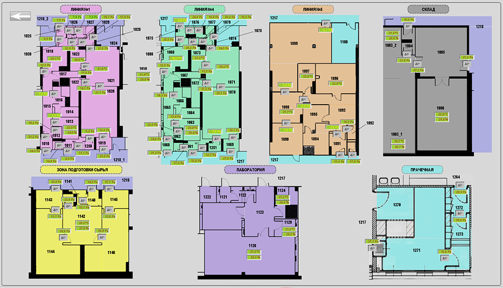 Figure 1: EMS project for a liquid dosage filling area.
Each monitoring and control element displays the current parameter value numerically and its status (alert level or action level) using color (the background color of the parameter field). Each monitored object has a properties window (Figure 2) that shows the current parameter values, their statuses and the permissible limits (setpoints).
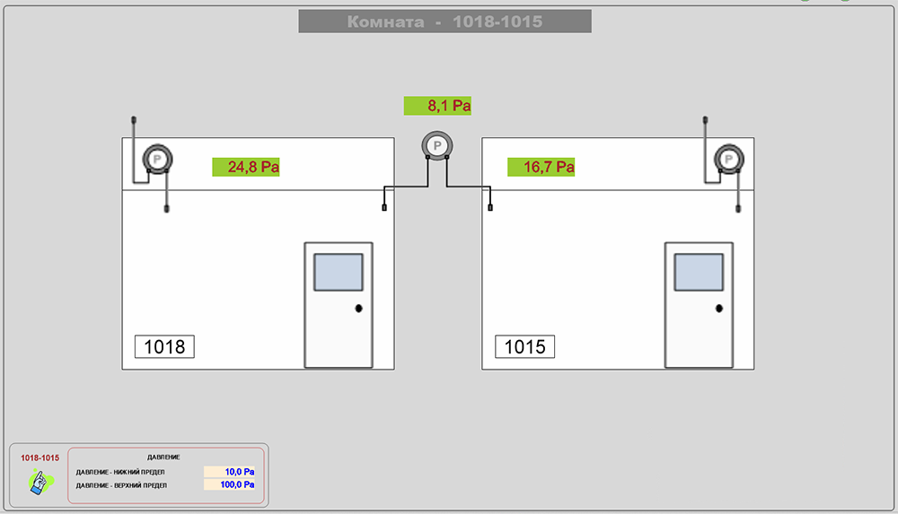 Figure 2: Object properties window.
The system can display current (Figure 3) and historical (Figure 4) alarm events, parameter trends (Figure 5) and log user activity as an audit trail (authentication, actions, changes) (Figure 6, 7, 8).
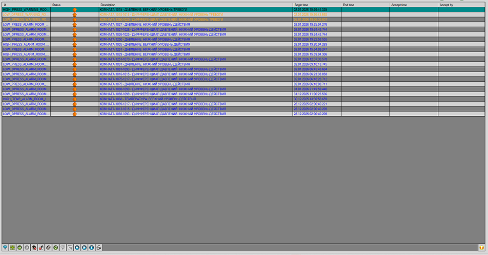 Figure 3: Active alarms.
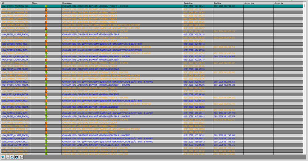 Figure 4: Alarm history.
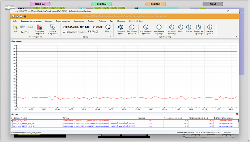 Figure 5: Trends.
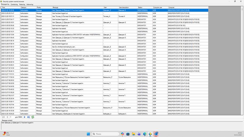 Figure 6: Login audit trail.
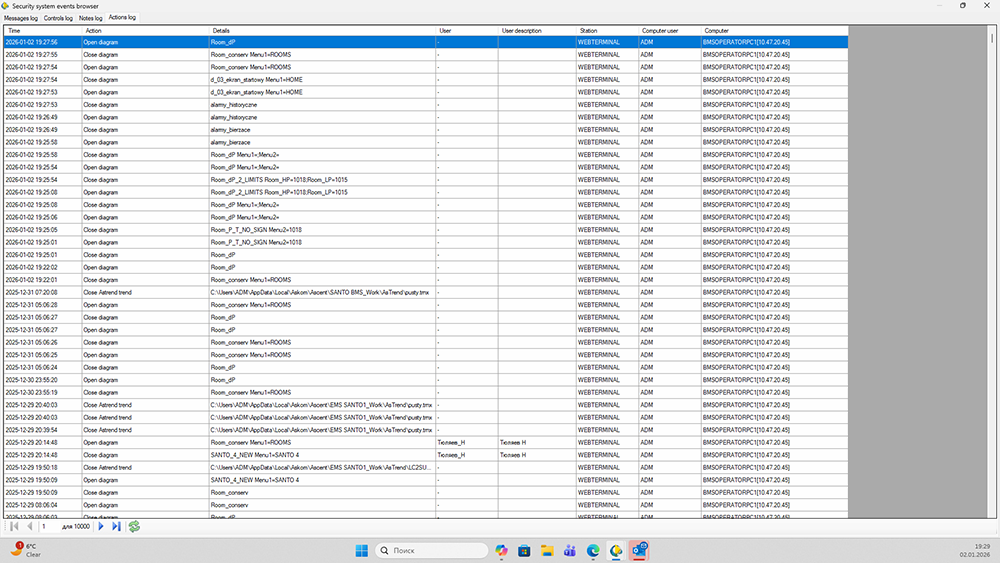 Figure 7: User activity audit trail.
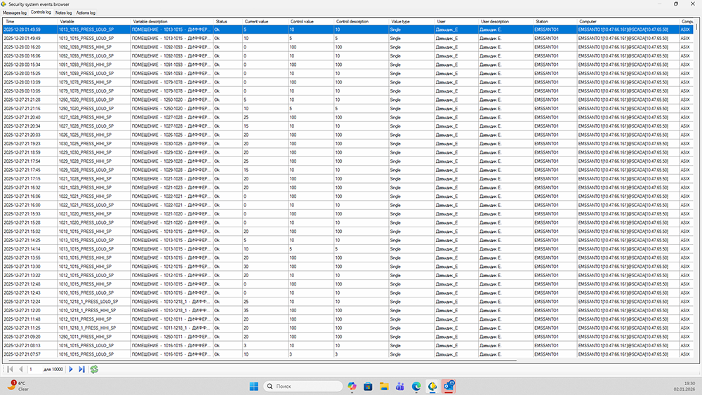 Figure 8: Change audit trail.
 Figure 9: EMS network topology.
Physical layer and system resilience
EMS network topology is shown in Figure 9. The core element of the system is the programmable logic controller (PLC). It collects and processes information from sensors and manages alarm situations. This is the brain of the system, capable of operating independently of its other elements, which is important to note. The PLC must provide the full functionality of any system (primary data processing, monitoring, control and setpoint storage). SCADA and the human-machine interface (HMI) panel should be assigned only those functions that do not affect the system’s ability to operate in a critical situation (information display and changing setpoints).
This topology provides three‑stage redundancy for system operation. If the SCADA client layer fails, full functionality is retained on the server, with limited functionality available via the HMI panel and the signal tower. If the connection to the server is lost, visualization and control remain available from the HMI panel, and monitoring continues via the signal tower. If the server is lost, the HMI panel still preserves (although limited) system functionality through the signal tower. This approach provides both multilevel control of the system (SCADA operator, line operator) and increased fault tolerance (SCADA system, HMI panel, signal tower).
EMS requirements
EMS requirements can be conditionally divided into noncritical and critical. Noncritical requirements are usually driven by experience with existing systems, internal corporate standards and the human factors of information perception. Critical requirements include the requirements of industry standards (e.g., GMP, GAMP, ISO, ALCOA+, data integrity), as well as requirements for EMS hardware/network architecture and cybersecurity.
Noncritical requirements include colors, fonts, shapes and sizes of user interface (UI) elements, single window versus multi-window layouts, localization and either an intuitive design (a floor plan with values and statuses displayed in the rooms) or a more minimalist one (a list of rooms and fields with the parameter values).
Critical requirements:
- PLC polling interval
- Data archiving interval
- Availability of local visualization and control elements that duplicate SCADA information (HMI panels, signal towers) • Data backup
- Reporting in electronic and paper formats
- System users and access rights
- Automatic logout
- Lockout after multiple failed login/password attempts
- User action comments
- User action confirmation
- Logging of user authentication
- Logging of user changes
- Logging of user actions.
EMS in the automation pyramid
Architecturally, an EMS occupies Levels 0 through 2 of the automation pyramid — from field level to SCADA. At the same time, it almost always interfaces with the manufacturing execution system (MES) and corporate reporting (quality, production, audits). Therefore, an EMS engineer must be a T‑shaped professional: deeply knowledgeable in PLCs, SCADA and communication protocols, while being confident in adjacent areas: electrical engineering, industrial Ethernet, server infrastructure, backup and basic cybersecurity principles.
Wrapping up
EMS is one of the most hands‑on and practical automation systems in pharma. It is simultaneously about engineering, regulatory requirements and operator convenience. Proper architecture (local logic in the PLC, redundancy, correct logs and reports) directly improves product quality and reduces the risk of deviations.